Knowledge
What is the difference between a differential probe and a regular probe?
In the field of electronic measurement, oscilloscope probes serve as the crucial bridge connecting the circuit under test to the oscilloscope, and their performance directly affects the accuracy and reliability of waveform measurement. There are various types of oscilloscope probes, among which high-voltage differential probes, with their unique advantages, are widely used in high-voltage floating ground scenarios such as switch-mode power supplies, new energy, and power electronics. However, the current market is filled with a wide variety of differential probe brands, with significant differences in performance indicators (such as bandwidth, common-mode rejection ratio, input impedance, etc.), often leading to distorted waveforms measured by engineers and making it difficult to obtain true circuit signals, thus posing challenges for debugging and fault detection.
I. Common Single-ended Probes: Principles, Characteristics, and Limitations
Common single-ended probes are the most basic and commonly used type of oscilloscope probe, designed around the concept of "ground measurement", and are widely used in low-voltage, common-ground scenarios for signal observation.
1. Core Working Principle
The measurement logic of a single-ended probe is "signal - ground" voltage difference detection: during measurement, the signal end of the probe needs to be connected to the "signal point" in the circuit, while the reference end of the probe (usually achieved through the oscilloscope's ground clip) must be connected to "ground" (which is typically connected to the oscilloscope's housing and the earth). The waveform ultimately collected by the oscilloscope represents the voltage change of the "signal point" relative to "ground".

2. Typical Advantages
●Convenient operation: Only the signal end and ground end need to be connected, without the need for additional reference point matching, suitable for quick debugging and routine signal observation (such as IO ports and microcontroller pin signals in low-voltage circuits).
●Low cost: Relatively simple structure, without the need for complex differential amplification circuits, high cost performance, suitable for scenarios with low measurement accuracy requirements.
3. Key Limitations
The core issue of single-ended probes lies in their "ground reference" characteristic, making them prone to interference in complex circuits, mainly manifested in two aspects:
●Severe noise interference: The signal-carrying wire acts as an "antenna", easily picking up environmental electromagnetic interference (EMI), power supply noise, and other background noise, resulting in distorted measurement waveforms that do not reflect the true signal.
●Ground bounce problem: When there is a large current switch in the circuit (such as the MOSFET conduction / disconnection in a switch-mode power supply), the ground loop will generate an instantaneous voltage fluctuation (i.e., "ground bounce"), at which point the "ground" reference point of the single-ended probe is no longer a stable 0V, leading to measurement result deviations and even waveform distortion.
II. Differential Probes: Principles, Core Advantages, and Applicable Scenarios
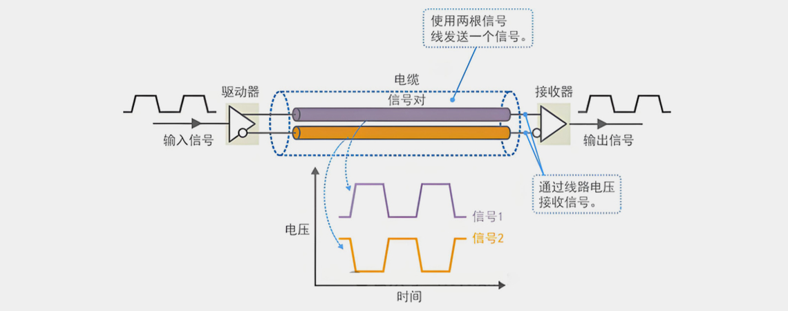
Differential probes are specialized probes designed to address the limitations of single-ended probes, based on the principle of differential amplification, capable of directly measuring the voltage difference between any two points without relying on "ground" as a reference, especially suitable for high-voltage floating ground and strong interference scenarios.
1. Core Working Principle
The measurement logic of a differential probe is "direct detection of voltage difference between two points": the probe's front end has two symmetrical signal input terminals (typically marked as "+" and "-" terminals), which are respectively connected to the two points in the circuit that need to be measured (such as the high-voltage side and low-voltage side of a switch-mode power supply, or the positive and negative poles of a differential bus). After the signal enters the probe, the internal differential amplification circuit performs a "subtraction operation" on the signals of the two input terminals, ultimately outputting the waveform of the "voltage difference between the two points" (i.e., "differential signal"), while suppressing the common noise (i.e., "common-mode noise") shared by the two input terminals.
This process can be simply understood as: if the two input terminals are simultaneously superimposed with the same noise (such as environmental EMI), the differential amplification circuit will "cancel" it out, retaining only the true signal difference between the two points, thereby achieving interference-resistant measurement.
2. Three Core Advantages ● Extremely strong anti-interference capability: With a high common-mode rejection ratio (CMRR, an indicator for measuring the ability to suppress common-mode noise, the higher the value, the better), it can effectively filter out environmental noise, ground noise, and other common-mode interferences. Even in strong electromagnetic environments (such as switch power supplies and motor drive circuits), it can output clear and stable waveforms.
● Supports floating ground measurement: It does not rely on "ground" as a reference point and can directly measure the voltage between two points that are not grounded (such as the floating ground end of high-voltage equipment and both sides of an isolated power supply), solving the problem that single-ended probes cannot measure floating ground signals.
● Precise timing positioning: As it directly measures the signal between two points, it avoids the timing deviation caused by the ground loop delay of single-ended probes. It is particularly suitable for timing analysis of differential buses (such as CAN, EtherCAT, USB), ensuring the measurement accuracy of signal edges and phase differences.

3. Typical application scenarios
● Switching power supply debugging: Measuring high-voltage floating ground signals such as the drain-source voltage of MOSFETs and the primary and secondary voltages of transformers;
● New energy field: Voltage measurement of high-voltage circuits in electric vehicles (such as battery packs and inverters);
● High-speed differential bus testing: Differential signal integrity analysis of buses such as CAN, RS485, and HDMI;
● Strong interference environments: Scenarios with a large amount of electromagnetic interference, such as industrial control and motor drive.
