
Knowledge
Differential Probe High Frequency CMRR Variability Core Principle
一、Probe body: first look at these 4 internal causes
1. Parasitic mismatch in the input attenuation network
The parallel stray capacitance of the positive and negative attenuation resistors and the PCB wiring capacitance are only slightly different, and the problem arises. For picofarad ΔC, the difference in displacement current generated at high dv/dt switching nodes is very obvious-this is most typical in half-bridge and SiC/GaN tests.
2. Bandwidth and phase imbalance of the amplification channel
The amplitude-frequency and phase-frequency responses of the two differential amplifiers do not completely coincide at high frequencies. After the common mode signal passes through two paths, a phase difference is generated, which is equivalent to a differential mode output.
3. Probe Aging and Calibration Failure
Input capacitance drift, BNC connector aging, internal shielding damage, will quietly destroy the symmetry; after long-term use without zero (Auto Zero), static offset will be superimposed on the high frequency imbalance.
4. The upper limit of the probe bandwidth itself is there.
The CMRR marked in the manual is the indicator at the corresponding frequency, so don't just stare at the DC CMRR. Many differential probes drop quickly at CMRR above 10MHz-this is the specification itself, not a fault.
二、Wiring: The Number One Killer of High Frequency CMRR
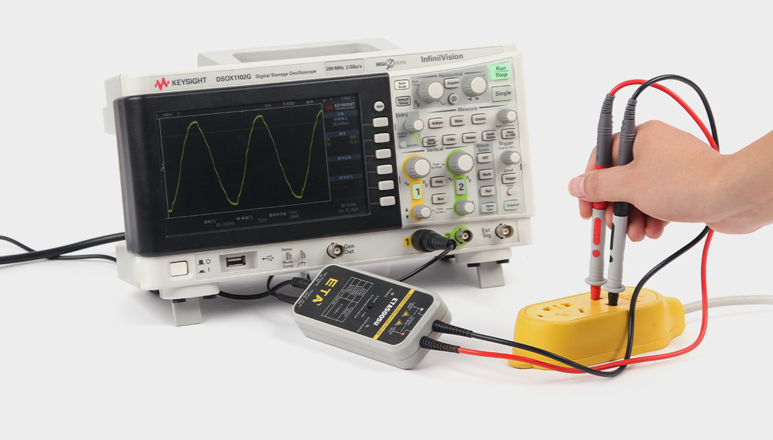
1. The positive and negative leads are not equal in length and are not symmetrical.
One long and one short, the inductance of the two leads and the parasitic capacitance to ground are different at once. Long leads will also pick up different space electric fields separately. The two wires must be of equal length and twisted tightly to minimize the loop area so that the coupling of the external electric field to the two wires is consistent.
Common mistakes: 1 a short straight needle and the other 1 a long alligator clip wire; The two wires are loosely separated and have different directions.
2. Lead wire too long, hanging too long
The longer the lead, the greater the capacitance to ground and the loop inductance, and the greater the difference in external EMI coupling. For nanosecond edge test, the suspended length of the probe shall be controlled to ≤ 5mm as far as possible, and direct welding on the pad is preferred.
3. Poor contact
The oxidation of the probe, the insufficient elasticity of the spring needle, and the virtual connection of the alligator clip will make the two contact resistances unstable and the dynamic impedance asymmetrical. Under high dv/dt, CMRR will follow a violent jump.
4. Wrong ground, ground loop
When the differential probe floats to measure, neither V nor V input can be connected to the oscilloscope ground. One end of the earth, the other end of the floating ground, will directly destroy the differential balance, CMRR on the spot collapse. When multiple probes measure at the same time, different probes are connected to different ground, and a ground loop will be formed-ground bomb noise is injected in the form of common mode, and then converted into differential mode spikes due to asymmetry.
5. Probe cable is placed asymmetrically
The probe host and BNC cable are close to the power board while far away. The two input lines are attached to the high-voltage node on one side and far away on the other, so the electric field coupling is naturally unbalanced.
三、Test fixtures: the most overlooked source of asymmetry
1. Fixture-to-ground parasitic capacitance asymmetry
The copper foil, PCB pad, and supporting medium on the fixture will make the V-to-ground capacitance and the V-to-ground capacitance unequal. Even if ΔC is only 1 ~ 3pF, under the high-voltage fast-edge common-mode voltage, the displacement current difference will pull out obvious pseudo-differential mode spikes-which can easily be misjudged as device ringing or spikes.
Typical scene: half-bridge clamp upper tube and lower tube pad have different ground areas, and the metal bracket is biased to one side.
2. Inductance mismatch caused by trace and copper foil
The path inductances from V and V to the measured point are inconsistent, the high-frequency impedance Z = jωL does not match, and the common-mode signal generates different voltage drops in the two paths.
3. Defects in shielding design
One-sided shielding and shielding plate are only close to one of the probes. The metal clamp shell is only connected to one side of the reference point, which will cause unbalanced electric field coupling.
Correct approach: the use of symmetrical metal shielding, shielding layer single point grounding, do not connect the shielding layer to either end of the differential input.
4. Fixture load asymmetry
The extra capacitor and resistor on the fixture are only connected to one of the differential input terminals, which directly destroys the original input impedance balance of the probe.
5. Coupling differences due to multiple test points
Other power traces and buses on the fixture are close to one of the differential leads, and the dV/dt electric field interference on the two paths is inconsistent.
四、4-Step Quick Self-Test: Distinguish"DUT True Waveform"Or measurement artifact"
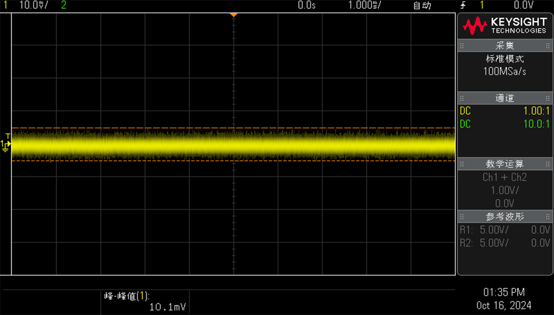
The following small test can separate the real waveform of the device from the pseudo differential mode peak introduced by the probe fixture. The double pulse and half bridge tests are very useful:
Step 1:The V and V of the differential probe are shorted together and connected to the same common mode fast edge signal at the same time. Ideally, the output should be close to 0.
Step 2:If the output has obvious spikes or glitches, the high frequency CMRR is not enough.
Step 3:Do double twisted short line again, remove the fixture and test again. If the waveform becomes significantly smaller, the problem is with the wiring or fixture.
Step 4:The waveform remains unchanged after being replaced by a short line, that is, the high frequency CMRR of the probe itself is insufficient, or the inside has been damaged.