
Knowledge
Influence of High-voltage Differential Voltage Probe on Test Circuit
High-voltage differential probes are commonly used measurement tools for electronic test engineers, and play an irreplaceable role in floating systems, high-voltage circuits, and differential signal measurement scenarios. Many users will have questions: differential probe has two input terminals, can it be used to measure conventional single-ended signal?
Conclusion: It can be measured, but the operation mode is exquisite, and there are potential risks and limitations of use.
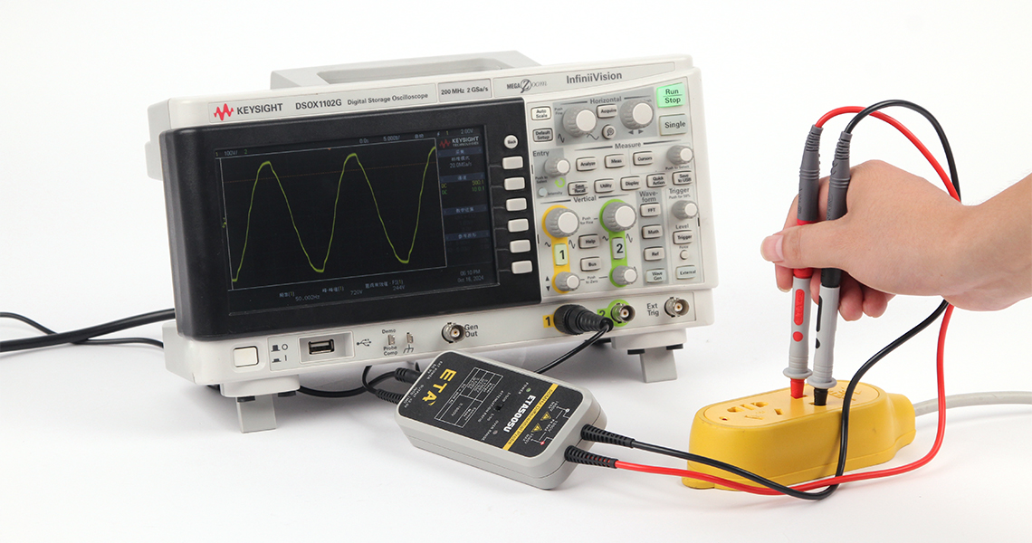
1.Differential Probe and Single-Enended Signal Fundamentals Definition
The differential probe is an active probe. The core principle is to collect the voltage difference between two test points and convert the differential signal into a single-ended output signal that can be recognized by the oscilloscope.
Single-ended signal: The signal voltage is defined with the common reference ground as the reference. Most of the circuit signals, such as TTL level, IO output of single chip microcomputer and conventional operational amplifier circuit, are single-ended signals.
2.Two connection methods for measuring single-ended signals with differential probes
Mode 1: the positive input terminal is connected to the signal, and the negative input terminal is connected to the reference ground
The positive end of the differential probe is connected to the measured signal point, the negative end is connected to the circuit reference ground, and the probe directly collects the signal-to-ground pressure difference, that is, the target single-ended signal.
In principle, the scheme is feasible, and the oscilloscope can restore the waveform normally. In low-voltage scenarios (3.3V, 5V digital signals, low-frequency analog signals), if the passive probe is not at hand, this scheme can be temporarily used to replace the test.
Mode 2: the negative input terminal is suspended (❌Not recommended)
It is not recommended to use the operation mode of only positive terminal signal and negative terminal floating.
The differential probe input is a balanced and symmetrical structure, and the negative end will lose the common mode suppression ability, which is very easy to introduce a large amount of environmental noise. The suspended pin is equivalent to the receiving antenna, picking up space electromagnetic interference, resulting in serious waveform distortion and measurement distortion.
3.Limitations of use and potential risks
Although the differential probe can temporarily measure single-ended signals, it does not belong to the standard test scheme and has a number of risks:
· High voltage safety hazard
The range of high voltage differential probe can reach hundreds of volts to thousands of volts. If it is used to measure high-voltage single-ended signals (such as 310V DC after rectification), the positive terminal is connected to high voltage and the negative terminal is grounded. Once there is a potential difference between the circuit to be measured and the oscilloscope protection ground, an abnormal current loop will be formed through the negative terminal of the probe, causing equipment damage and even electric shock risk.
Supplement: Ordinary passive probes are prohibited from directly measuring floating ground high voltage, while high voltage differential probes were originally designed to solve floating ground common mode measurement scenarios.
· Common mode voltage causes dynamic range bottleneck
The range indicated by the probe is the differential voltage range. For single-ended measurements, the differential voltage is within range, but the common-mode voltage at both ends to ground may be asymmetric.
Example: 5V single-ended signal with common mode of 100V to ground, 105V to ground at one end and 100V to ground at the other end. The differential signal is only 5V, but the single-ended ground voltage approaches the maximum common-mode withstand voltage of the probe, and long-term use will cause damage to the probe.
· Bandwidth vs. Noise Bottom Disadvantage
The high-voltage differential probe is optimized for high-voltage and high-common-mode conditions. The mainstream bandwidth is concentrated in 25MHz ~ 100MHz, and the noise index is generally weaker than the passive probe at the same price of 100MHz ~ 500MHz. High frequency, small amplitude single-ended signal test, passive probe waveform signal-to-noise ratio is better.
· Input load effect
Differential probe input impedance is high, but some models input capacitance is greater than 10 x passive probe. When testing high-frequency signals and high-impedance nodes, the load effect will disturb the original circuit and change the true state of the measured signal.
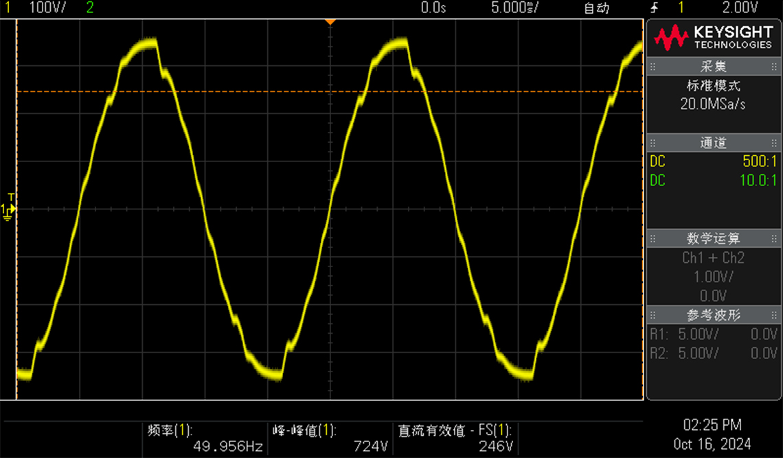
4.Summary and test selection recommendations
Conclusion: Differential probes can measure single-ended signals, but are not recommended as a routine solution.
When only the low-voltage single-ended signal is temporarily tested and no other probe is available, the method of [positive termination signal, negative termination circuit ground] shall be adopted. Daily test priority to follow the selection principle:
- Low-voltage single-ended signal (<100V): Passive probe is preferred, with simple operation, sufficient bandwidth and good stability;
- Floating circuit, with large common-mode voltage signal: select high-voltage differential probe (matching design purpose);
- High-voltage single-ended signal to ground: if there is a potential difference between the measured ground and the oscilloscope protection ground, differential probe or oscilloscope isolation channel must be used, and ordinary passive probe is strictly prohibited.