
Knowledge
Negative Current of Pulse CT: Analysis and Troubleshooting
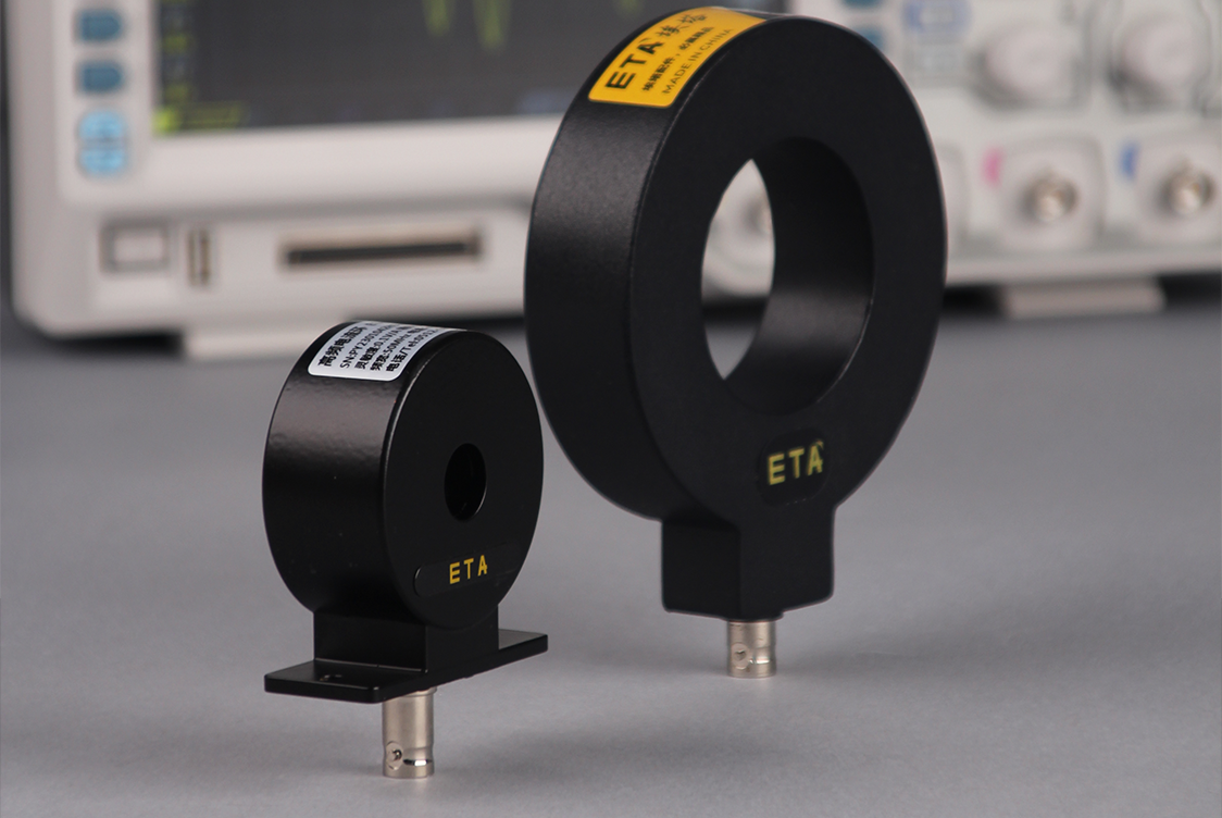
In applications such as switch-mode power supplies, power electronic conversion, pulsed discharges, and transient characterization of devices, passive through-core pulse current transformers are widely used due to their advantages, including electrical isolation, wideband response, and the ability to capture large transient pulses. However, many engineers encounter the same question when setting up or debugging test platforms:The current direction predicted according to the circuit schematic diagram is clearly positive, but the oscilloscope continues to read negative values after conversion.
Many people’s first reaction is that the sensor is damaged or the wiring is incorrect. In fact, negative current is rarely caused by a single reason, it is often the result of the superposition of polarity definition, oscilloscope configuration, magnetic core electromagnetic characteristics and the real current direction of the loop 4. In this paper, we do not recommend models, but only take passive core-piercing pulse current transformers as general objects, disassemble the generation mechanism of negative current layer by layer, clarify the basic concepts that are easy to be confused, and give the sequence of investigation that can be carried out directly.
一、 Basic Cognition: Polarity Marking is a Trap in Itself
Passive through-core transformers rely on electromagnetic induction to work, can not measure constant DC, can only respond to alternating current and pulse current. And most of the polarity confusion, initially comes from the printed arrow on the shell.——There is no uniform standard for the meaning of arrows in the industry.
Two mainstream labeling logics coexist for a long time:
Identification 1: Arrows represent the direction of electron flow.When threaded with this dimension, the phase of the induced output voltage is naturally opposite to the current direction defined by the textbook.
Marking 2: Arrow represents the direction of positive charge current in engineering.Consistent with the theoretical definition of the circuit, a positive reading is obtained by threading the schematic.
The current direction defined by the textbook is the direction of positive charge movement, which is exactly opposite to the actual direction of electron movement. Once the sensor uses the first label, and the user directly threads the line according to the schematic diagram, the final conversion is the negative current.You can't take the current definition of circuit theory to match the shell arrow.,This is the most likely to be skipped, but also the most likely to step on the bottom of the contradiction. When using the 1 sensor for the first time, it is much more efficient to power on and do a phase calibration first than to doubt the hardware afterwards.
二、 Measurements show the cause of the 5 large core of negative current
According to the field frequency from high to low, negative current can be classified into the following five categories. The following table gives clues to the quick judgment, followed by an itemized explanation of the mechanism and disposition.
| Cause | Waveform characteristics | Disposal direction |
| The penetration direction is opposite to the calibration polarity | The whole waveform is turned upside down, and the contour is complete without distortion. | Reverse through wire; or open channel reverse phase, and note in report |
| Oscilloscope parameter configuration | The forward current is directly displayed as negative, and the amplitude may be distorted synchronously. | Turn off channel inversion, cut high resistance input, select coupling according to signal characteristics |
| True reverse current of loop | The shape is normal, negative values appear in specific working phases | No correction, combined with the topology to determine the freewheeling, discharge or oscillation phase |
| Flux accumulation (magnetic sag) | The pulse flat top is continuously tilted, and the baseline is slowly shifted. | Control pulse width and interval, add bias winding if necessary |
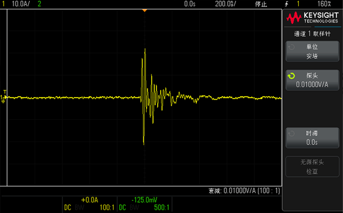
| Grounding and Electromagnetic Interference | Many burrs, severe noise and continuous zero offset | Single coaxial line, shortened ground wire, single point grounding, far away from interference source |
Cause 1: the lead direction is opposite to the calibration polarity of the transformer (the highest incidence)
The direction in which the conductor passes through the magnetic ring directly determines the phase of the induced electromotive force. Determination method is very simple:Keep the working state of the circuit unchanged, and reverse the measured wire through the transformer aperture.If the waveform is turned upside down as a whole, the current is switched synchronously, and there is no change in the shape, it is a pure polarity matching problem, and the sensor hardware itself is good.
The threading direction shall be adjusted preferentially on disposal; if the field wiring is limited and cannot be changed, the oscilloscope channel inversion function can be enabled to correct the display.But inversion only changes the waveform shape, not the original physical facts.,This 1 must be noted when writing the test report to prevent the follow-up personnel from misreading the original phase information.
Cause 2: Introduction of artificial phase inversion in oscilloscope channel parameters
Many negative readings are not from the loop, but the illusion caused by the instrument settings. During investigation, check the following three items in turn:
Channel Invert is turned on by mistake.After the start of all the acquisition waveform phase reversal, the positive current directly output negative, which is the most easily ignored one.
Input impedance mismatch.Most passive pulse transformers have integrated terminal resistors inside, requiring oscilloscopes to use high-impedance input; If it is miscut to 50Ω, it will form impedance parallel voltage division, amplitude distortion and baseline offset, inducing abnormal reading symbol.
Improper choice of coupling mode.Passive transformers generally have low-frequency cut-off characteristics, long-time unidirectional pulse measurement should use AC coupling to suppress drift; DC coupling under the baseline drift component superimposed on the signal, easy to make the overall waveform bias negative interval.
Cause 3: the real current flow direction of the loop is inconsistent with the previous prediction.
Do not equant a negative current uniformly as a measurement error. In the power electronic circuit, the current direction will change dynamically with the working phase: power device freewheeling, capacitor reverse discharge, buffer absorption circuit, LC oscillation and bidirectional pulse conditions, the reverse current is the normal working state of the circuit.
Distinguishing skills: after reverse threading, the positive and negative currents flip synchronously, and the waveform shape is not distorted, indicating that negative values reflectTrue current direction,instead of measuring faults. This type of data should not be discarded because it is directly related to power flow and device loss analysis.
Cause 4: magnetic flux accumulation under unidirectional pulse (magnetic sag effect)
Passive transformers rely on alternating magnetic field to induce signals and cannot balance the unidirectional continuous magnetic flux by themselves. When the unidirectional pulse is applied for a long time, the magnetic flux inside the magnetic core accumulates continuously, which shows the typical sagging of the pulse flat top:The top of the pulse continues to tilt, the baseline slowly shifts, the waveform as a whole falls into the negative range, and the average reading continues to be negative.A single surge pulse, long time unidirectional drive test is a high frequency scenario.
There are 3 optimization methods: reasonable control of pulse duration, for the magnetic core to reserve enough magnetic flux natural reset interval.
The main point of distinction from genetic 1 is the waveform profile:The simple polarity reversal is the overall translation and the shape is unchanged; the magnetic flux accumulation will bring distortion and flat top tilt at the same time.
Cause 5: poor grounding and electromagnetic interference caused by zero offset
Loose contact of coaxial BNC cable, multi-point grounding of test system and strong electromagnetic field interference near the bus under test will superimpose additional DC offset on the induction signal, causing zero drift and forming a seemingly reasonable false negative current. This type of problem is typically characterized by a significant increase in noise and burrs, and changes in readings after changing lines and positions.
Optimization scheme: select high-quality coaxial signal line, shorten the test ground wire, adopt single point grounding for the whole test system, and keep the probe and signal line away from strong interference sources such as frequency converter and contactor.
三、 Lateral extension: the polarity logic of the three types of current sensors is not interoperable
For current probes with different principles, the polarity rules cannot be applied directly. Translating the experience of using one type of product to another is a common source of persistent phase reversals.
| Sensor type | Polarity rules | Usage recommendations |
| Passive pulse current transformer | There is no unified national standard for arrows, and the two marking methods coexist. | Be sure to energize the calibration phase for the first time. |
| Active Hall Current Probe | Industry norms are relatively uniform, more follow the positive charge current direction | Can be directly threaded according to the schematic diagram, less polarity confusion |
| Rogowcell coil | The polarity is determined by the coil winding process, and the rules of each manufacturer are different. | Reconfirm phase when changing manufacturer or range |
The easiest pit to step on is to directly copy the operation mode to the passive transformer after getting used to the logic of the Hall probe, so the phase reversal appears repeatedly, but the hardware is always suspected.
四、 Standardized rapid troubleshooting process
Converge the above causes into a reusable inspection sequence: first eliminate the instrument and wiring, then judge whether the polarity is mismatched, and finally attribute it to the magnetic core and the real current direction. The passing criteria for each step are clearly written as follows to facilitate handover to others for review:
No-load baseline verification.Disconnect the current of the tested circuit and observe the baseline of the oscilloscope: zero fault will be eliminated if it is straight and free of drift; If there is still deviation, first deal with the instrument and grounding, and then go down.
Polarity verification test.The wire reverses through the transformer, and whether the positive and negative currents flip synchronously is the key evidence to determine the polarity matching problem.
Parameter review.Confirm that the high impedance input, the channel inversion is closed, and the coupling method matches the signal characteristics.
Wiring inspection.Confirm that only a single current-carrying wire passes through the magnetic ring, and the incoming and outgoing cables are arranged separately. Resolutely avoid the reciprocating wires passing through the same ring-the magnetic fields cancel each other out, which will not only greatly attenuate the amplitude, but also cause phase disorder and random positive and negative readings.
Waveform feature analysis.If the morphology is intact, only positive and negative reversals are classified as polarity; flat top tilt and continuous baseline drift are classified as magnetic flux accumulation; dense burrs and severe noise are classified as grounding and interference.
五、 Key points of avoiding pit in engineering application
Pre-test Platform Planning
When the tooling is built, the adjustment space is reserved for the conductor to pass through, and the ability to pass through is regarded as a constraint of structural design. When the wiring cannot be modified, you may use an oscilloscope to temporarily invert the signal for display; however, be sure to save and retain the original acquired data, clearly documenting the waveform processing method.
Principles of Data Interpretation
The sign of the current represents the direction of charge flow, which is directly related to the power flow direction and the device loss analysis. Negative values should not be simply judged as measurement failure, let alone discard phase information at will in order to look pleasing to the eye.
Clear sensor measurement boundary
Passive pulse transformer is good at transient alternating signal acquisition, in the continuous one-way large pulse scene, must face up to the measurement error caused by magnetic droop, can not directly take the average waveform as the conclusion basis.
Test Document Normalization
When recording the test conditions, the 4 items of information shall be marked synchronously: the relative position of the wire threading direction and the arrow of the transformer, the input impedance of the oscilloscope, the coupling mode, and whether the waveform inversion is enabled. These 4 items determine whether the same data can be reproduced by a third party, and are also the first thing to look at when checking and retesting.
One word conclusion:
Negative currents are first treated as signals to be verified rather than as faults to be repaired. Reversing a conductor once, verifying the channel settings once, and examining the waveform profile once—these three causes can usually be distinguished within a few minutes.